| 12.1 Introduction |
| 
| 12 UML to RSL translator |
| 
| 12.3 Distribution Files |
|
| 12.2 General Description of UML2RSL |
12.2 General Description of UML2RSL
The overall pattern of use of UML2RSL is
- Draw a UML class diagram using a graphical tool
- Export the class diagram in XML
- Use UML2RSL to convert the XML file into a collection of RSL files
This is explained in more detail below.
UML2RSL has been developed in Java, which makes it a portable
tool. As is shown in figure 12.2, it takes as input an XML
file produced by a UML-based graphical tool, where all the information
about a class diagram has been stored; it parses the XML file and, if
the input is syntactically correct, translates the class diagram to an
RSL specification based on the proposed semantics in [9].
The input XML file must be compliant with the XMI DTD version 1.2.
There are several commercially available UML-based graphical tools
having among their features the possibility of generating this kind of
file. Free tools can be downloaded from
http://www.magicdraw.com and from
http://www.gentleware.com. The
examples presented in this guide have been produced using the version 7.5
community edition of the MagicDraw tool.
To decide if the class diagram is syntactically correct, UML2RSL bases
the analysis on a set of rules given in [9].
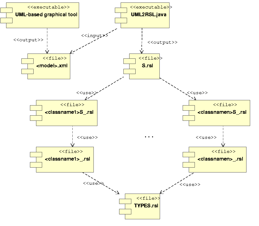
The resulting RSL specification is modular. It consists of several
RSL files. One of them is named S.rsl and it corresponds to the
top-level module. This module has the specification of the model
represented by the whole class diagram. S.rsl uses a set of
auxiliary modules. Each of them has the specification corresponding
to one of the classes in the class diagram. These modules receive as
name the corresponding class name in upper case, followed by
S_. Each RSL module generated for a class use, in turn, a lower level
module where the specification for one object of the corresponding
class is given. They receive the same name than the class in upper case
followed by _. Finally, each one of these lower
level modules uses, in turn, a module named TYPES.rsl where all
the abstract types present in the diagram are defined. There is a
variation in the module structure of the specification when
generalization relationships or templates
classes are used as we will see in sections
12.6.2 and 12.6.3.
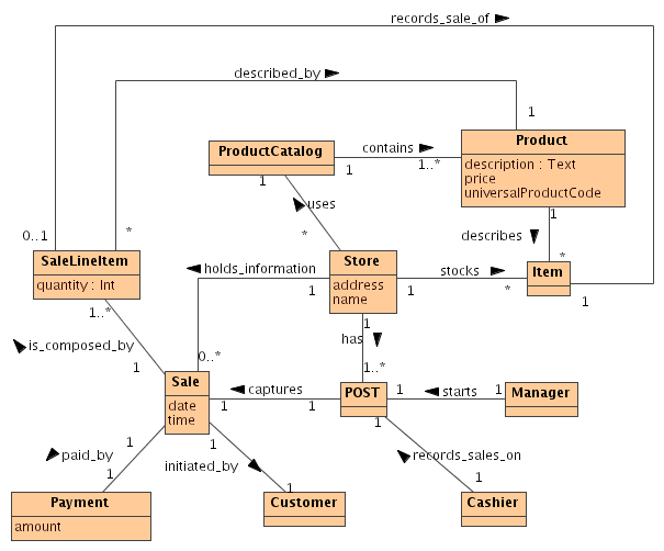
In figure 12.2 we give a class diagram in UML taken
from [10] for a simple system: a Point of Sale System. This
example serves to illustrate the resulting specification produced by
the translator and to show the corresponding RSL dependency graph.
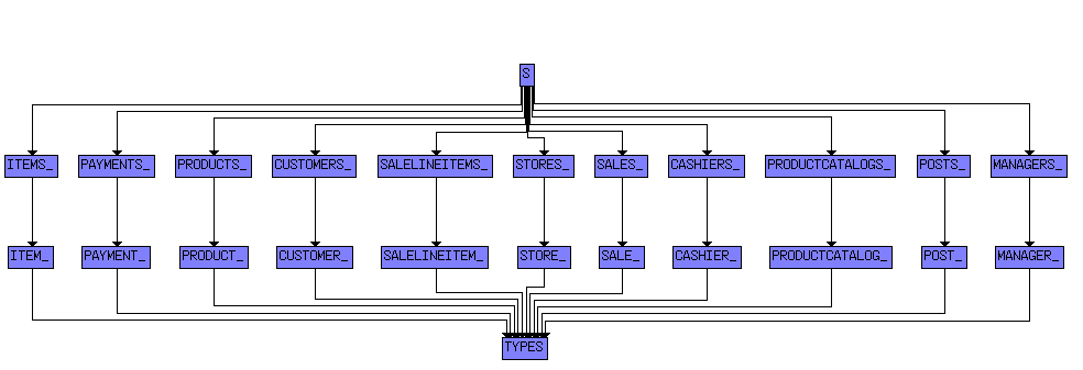
The produced specification consists of the top-level module S
which uses SALES_, SALELINEITEMS_, MANAGERS_, PRODUCTS_,
PRODUCTCATALOGS_, PAYMENTS_, POSTS_, CASHIERS_,
ITEMS_, CUSTOMERS_, and STORES_. Each of them
correspond to a class in the class diagram and they use respectively SALE_,
SALELINEITEM_, MANAGER_, PRODUCT_,
PRODUCTCATALOG_, PAYMENT_, POST_, CASHIER_, ITEM_,
CUSTOMER_, and STORE_ that have the specification for an object
of the corresponding class. Finally, the last ones use the module
TYPES. Figure 12.2 below shows the dependency module graph
produced by the RSL tool for the specification obtained from the class
diagram.
Chris George, April 17, 2008
| 12.2 General Description of UML2RSL |
| 12.1 Introduction |
| |
| 12 UML to RSL translator |
| |
| 12.3 Distribution Files |
|